My experiments with IoT – “Meeting with Pi”
|
Ingredients: Little bit of nodeJS, ½ teaspoon raspberry pi. 🙂 |
When I heard the word IoT from one of my colleagues back in 2012, it was just like a piece of tech which seems to be very far from my world. Later when I started working with Arduino and raspberry pi in 2015, I realized the potential.
How it started
I am a graduate in computer science, with very little interest in electronics. During my college days, we had a paper on electronics and my score is “just pass”. My prime focus was behind programming languages and its concepts. Tried to learn many programming languages during the college days itself. It seems very easy for me to learn new languages as I tried to understand the concepts first, then the constructs.
It was in 2015 when one of my colleagues explained me about the working of raspberry pi. I was quite interested in it and there began the new phase of my learning.
The IoT Life
After hearing about raspberry pi, I decided to buy a pie. After a little research purchased a raspberry pi from amazon. My initial experiments included connecting the pi to my tv using HDMI and try different OS in it; not limited to raspbian ( default OS). Also tried berryboot, retro pie, XMBC in my PI. Used Pi for playing games as well as using it as a media hub.
Sooner I realized that I was deviating from the purpose that I bought Pi. All these things anyone can do. I need to try something unique, something innovative. This thought had driven me to the things world.
Who can learn IOT?
Anyone with fair knowledge of c++ / nodeJS, python, with a little common sense can create a world of things
Let’s begin
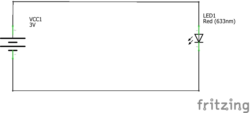
The basics that you need to understand here is current flows in a closed loop and not in an open loop. If you place a led in a circuit between the positive and ground terminal, led turn on.
In other words, binary one (1) can be used to represent where there is a voltage(+) and a binary zero(0) for ground. These 1’s and 0’s are the basics of electronics circuit and it is the basic building block of anything (IOT).
Basics of Raspberry Pi
There are different types of raspberry pi like Pi 2, Pi 3, Pi Zero etc.. Each of these differs each other with specifications like chipset, RAM size, USB ports, display ports etc. But in general, they have a set of pins which is called as GPIO (General Purpose Input Output) pins. Apart from the GPIO pins, there are specific purpose pins like clock pin, Ground pins, 5V Pin, 3.3V Pin. these pins have a specific purpose, where we can programmatically set the GPIO pin to the high state or low state. We can use c++, nodeJS, python for controlling the GPIO pins.

Image source : http://www.jameco.com/Jameco/workshop/circuitnotes/raspberry-pi-circuit-note.html
Each GPIO pin has a number associated with it. See the above pinout diagram for more details.
For now, we will use a small nodeJS script to work with Pi with the help of the rpio library (https://github.com/jperkin/node-rpio).
To install rpio library
npm install rpio
Below is a small nodeJS snippet to set the GPIO pin 12 ( GPIO 18 ) to high then to low 5 times every 500 milliseconds.
var rpio = require('rpio');

rpio.open(12, rpio.OUTPUT, rpio.LOW);

for (var i = 0; i < 5; i++) {
/* On for 1 second */
rpio.write(12, rpio.HIGH);
rpio.sleep(1);

/* Off for half a second (500ms) */
rpio.write(12, rpio.LOW);
rpio.msleep(500);
}
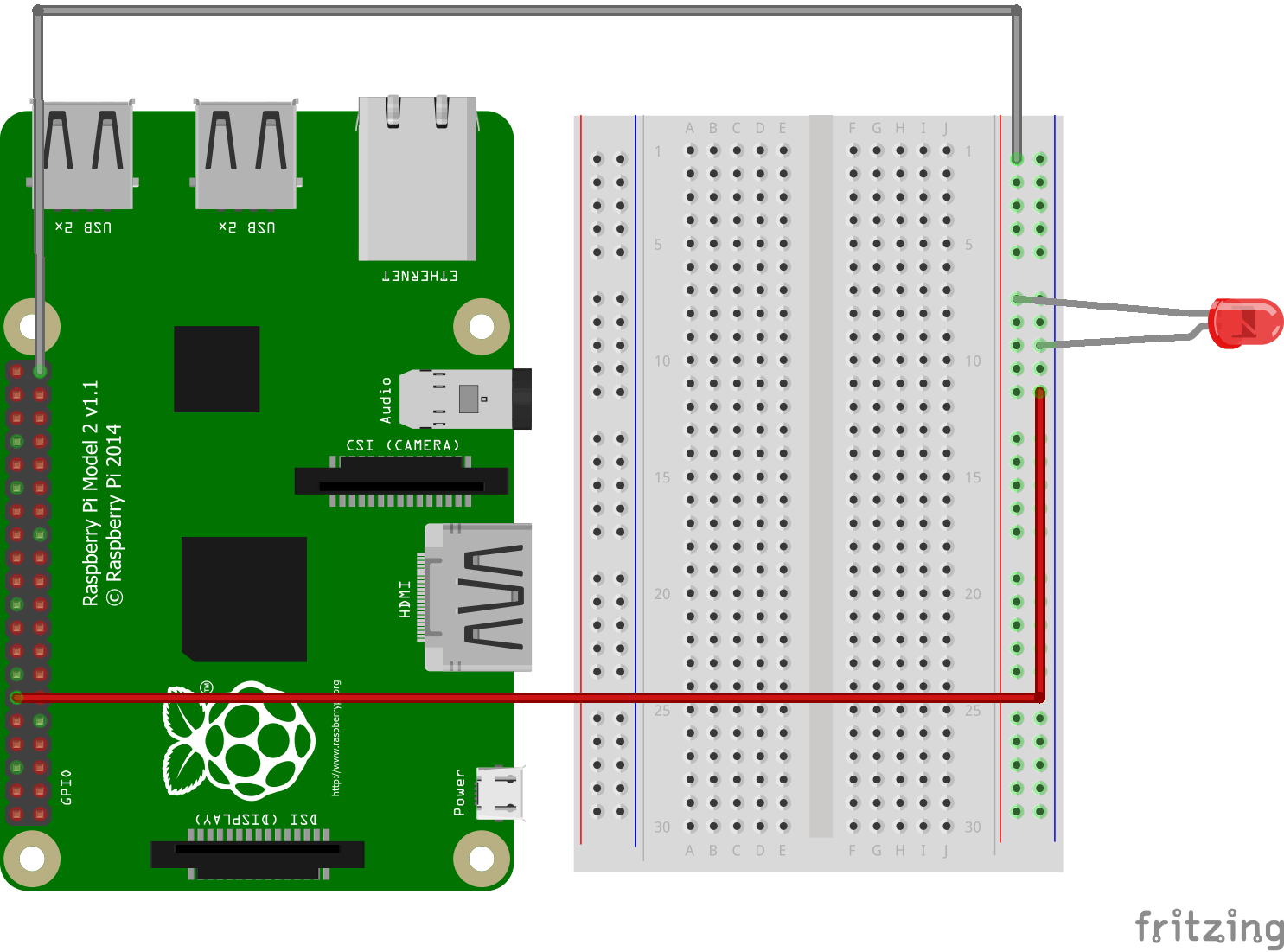
So if I connect a LED pin to the GPIO pin 12 ( GPIO, then LED will blink at an interval of 2 seconds
wow! We did our hello world on raspberry pi.
Coming back to how it worked,
rpio.open(12, rpio.OUTPUT, rpio.LOW);
The above code initializes pin 12 to output mode and sets the default value as zero.
rpio.write(12, rpio.HIGH);
The write method then keeps the pins high and low periodically, which turns the led blink.
Processing input
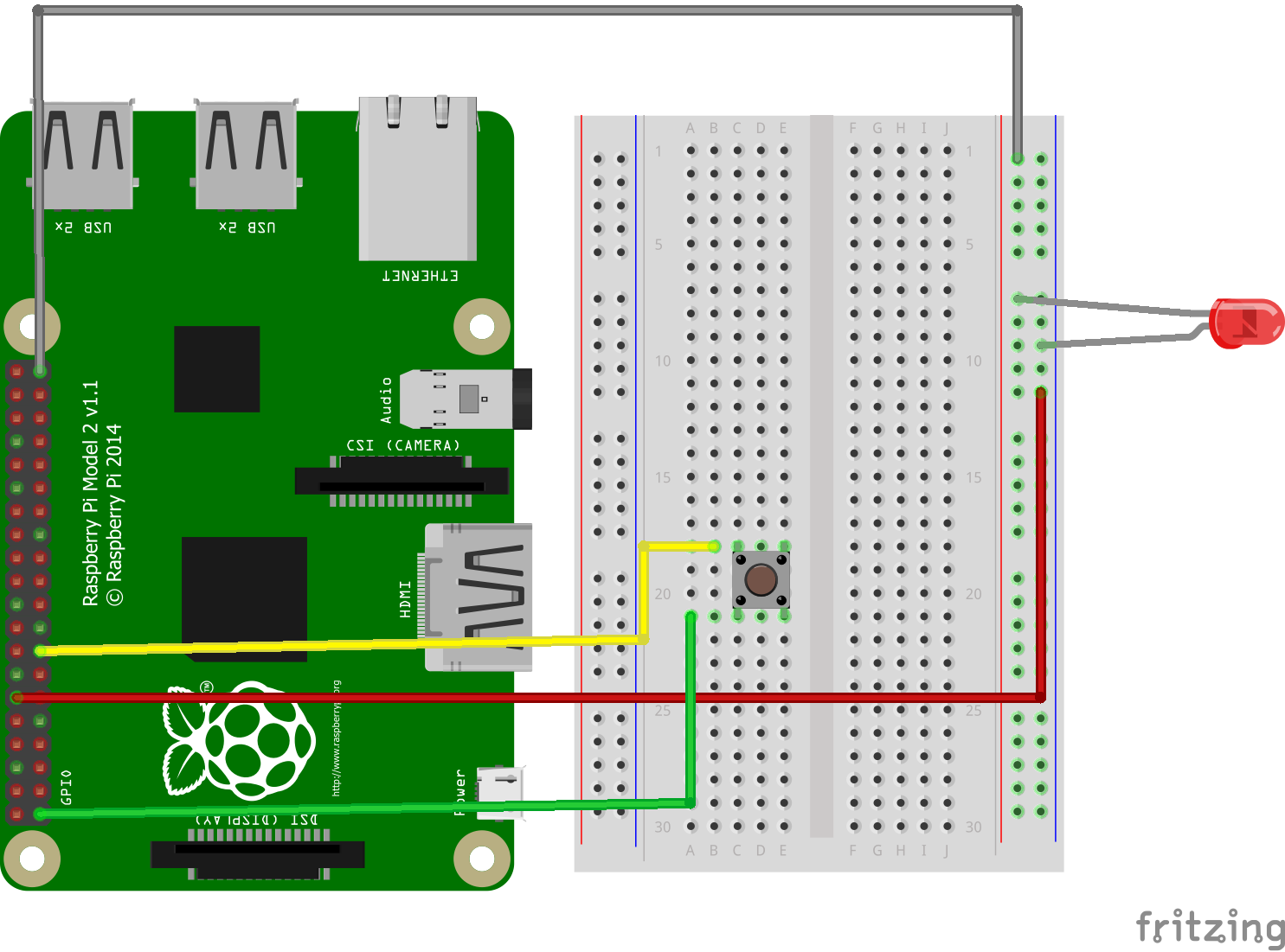
Now we have seen how to do output, let’s see how to control our logic. The same pin can be used as an input pin also. It is the reverse of what we did for blinking. We need to get the input from a button and if it is clicked then the led needs to be turned on.

var rpio = require('rpio');


rpio.open(15, rpio.INPUT, rpio.PULL_DOWN);
rpio.open(12, rpio.OUTPUT, rpio.LOW);

function pollcb(pin)
{
        var state = rpio.read(pin) ? rpio.HIGH :rpio.LOW ;
        rpio.write(12,state);
}


rpio.poll(15, pollcb);
On clicking on the button, it will make the GPIO pin 15 high, which is captured as a interrupt and the logic is executed, which will turn the led on.
As you see the way of initialization and usage is almost similar
This way you can control almost any sensor using raspberry pi / Arduino.
I will be coming up with a hello world post for Arduino.
Please share your feedback through the comment box.
Great start 👍nicely explained..